 |
|
![]()
![]()
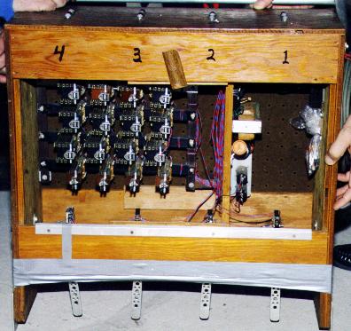
Here is a picture of our old 4 lane finish line made with mechanical switches and pinball machine relays. 1950's vintage we think. It's been acting up a lot over the last few years and has been difficult to set up and align. Certain lanes always seemed to have the advantage because of the mechanical switches used and tripped by the cars! The relays are used like flip flops.
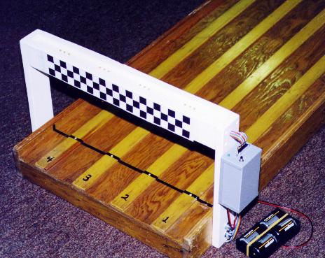
Below is a picture of our new, fully electronic, finish line. Light beams replace the mechanical switches and digital logic replaces the old-fashioned relays. It utilizes infrared sensors and PAL based logic. All the electronics are in the small gray box hanging on the side of the finish line. The infrared photo sensors are in the track and the infrared emitters and LED finish indicators are in the "tower". There are three LEDs for each lane. First place is indicated by one LED being on, second by two, third by three, and last or fourth place stays dark. Ties are also displayed, for example, a first place tie would light one LED for both first place lanes, the next place would light three LEDs, and last would be dark. This works up to a four way tie. With a 1.544 MHz oscillator we have never seen a tie nor have I been able to simulate one by breaking the light beams. It can only be done by either slowing the clock way down or wiring switches to simultaneously trip multiple lanes.
The schematic for our 4 lane finish line is available in this PDF file. The PAL equations, JEDEC file, and compile results are in this PAL source ZIP file. Thanks go out to Jay Gerbehy for providing a modified version of his Pack's 3 lane PAL equations.
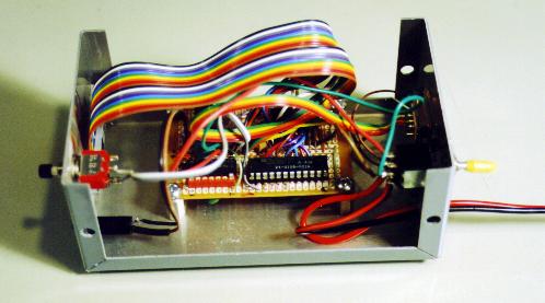
Only three ICs are needed for this project because all the logic is contained in the PAL. The other two ICs are a TTL clock (< 1 MHz or so, speed is not critical) and a comparator for the IR sensors. This allowed it to fit into a small project box with lots of room to spare.

Construction can be done in a myriad of ways, I'll outline how I did it though. You'll have to get the parts list from the schematic, I will explain a few parts below though.
LM339 is a quad comparator. Radio Shack p/n 276-1712 is one possible source.
The phototransistors I used were Radio Shack p/n 276-145A. They are infrared, though I did find that they were quite sensitive to room light also, so make sure they are installed in the track! They are a twin lead device and look just like a clear LED with a built-in plastic lens. The collector is marked with a flat spot on the round base of the plastic package. Specs say that the dark current is 100 nA and the light current is 20 mA. Use whatever you can find, be aware however that you might have to adjust the value of the 33K resistors which make up the other half of the voltage divider up or down depending on which detector you choose. Using these detectors with a 10K resistor prevents them from being sensitive to room light but you can't have the distance between the emitters and the track be more than 10 or 12 inches.
The emitters just need to be compatible with the detectors you choose. I used some high output infrared LEDs, Radio Shack p/n 276-143C. The cathode is indicated with a flat spot on the base of the round plastic package.
The 22V10 can be anything you can get programmed. I used some old through-hole parts, AMD 25 ns CE22V10. Speed is not at all critical in this application, just don't get carried away and use a 100 MHz oscillator for the project!
The oscillator can be anything in the 1 MHz range. I used a 1.544 MHz can oscillator because it's what I had laying around. You could also use a 555 timer with an RC but that's more components and wiring.
Though they are not shown on the schematic, you should add some bypass caps. Depending on how you wire it and what you use for a power supply, you should have at least a 10uF electrolytic on the circuit board where power enters along with a 0.1uF. You should also have one or two 0.1 uF capacitors bypassing each IC on the board. This will help cut down on noise problems that might crop up, though the circuit is simple enough that it should not be an issue either way.
That's it for the parts, on to the building. I bought a prototyping board (Radio Shack 276-150) PC board that has copper patterns etched on the back to make power hook up and many of the connections easier. You could wire wrap it, but I wanted it to be more durable for the long haul. The mechanical nightmare we used to use had to be over 20 years old and still worked (kind of) so I wanted this new electronic judge to last even longer.
I installed the ICs in sockets on the board and soldered everything else directly to the PCB. I installed the power switch, power LED, and reset switch on the electronics enclosure. The batteries, four D cells, are connected via a pig-tail lead. Four D cells have more than enough staying power. I could have gotten away with AA cells.
I decided to use connectors on the box that holds the electronics so that it could be easily separated from the track and finish for storage. I used a 20 pin dip (ribbon cable type connector) to connect to the finish which has the IR emitters (and their associated 47 ohm resistors) and the place indicator LEDs (and their resistors). I used a DB9 connector for the connection to the track IR detectors.
I added an additional diagnostic feature to my circuit which is not on the schematic. I connected the output of each comparator to a small LED (and 300 ohm resistor in series) mounted in the enclosure so I could test the status of each IR pair for alignment purposes. So the battery would not be drained further by an additional LED for each lane, I installed a momentary push button switch which needs to be pressed in order to use the diagnostic LEDs. It's a frill that you might want to add to yours, but I have not found it to be necessary during set up, the IR pair I'm using has great range and is easy to align.
One more thing I've thought of adding is a diode on the supply feed line, something like an IN4002, so that if the batteries get plugged in backwards accidentally the diode will protect the electronics from getting fried. It'll bring the voltage closer to 5V from the 6V batteries also. Suppose you could also power it with an AC adapter, but where we race extension cords would be a problem and batteries are more universal. I'd be afraid someone would plug in a 24V power supply instead of a 5 or 6 volt one.
Other than make sure that the detectors are perfectly in line so that each lane is equal and the building of the finish tower that houses the emitters and place indicator LEDs (see the mechanical drawing of ours), that's about it. Sorry I don't have time for a detailed and fully illustrated step by step instruction list, feel free to email me if you have any questions though.
Pack 180 4 lane finish line, Copyright © 1999 by Dan Roman and Jay Gerbehy. Permission is given to build and use a finish line based on this design to Boy Scout Troops and Cub Scout Packs. Commercial use or sale of this design is prohibited. Commercial use or sale of finish lines based on this design is also prohibited.